TERCCIndustrial insulation by TERUURequest a Quote

Chilled water

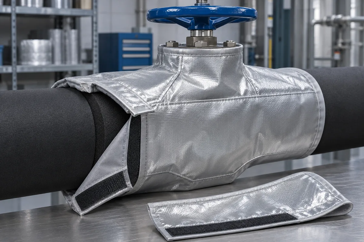
Removable chilled-water valve insulation covers

Plan a continuous vapour seal through seams, penetrations and pipe insulation transitions.

Chiller rooms and chilled-water valve stations where condensation is a concern.
Removable chilled-water valve insulation covers in silver vapour-control face with black transition
Silver vapour-control face with black transition · Design illustration

Follow the vapor seal across the valve

Review the stem collar, removable seam and both transitions to the adjacent pipe insulation.
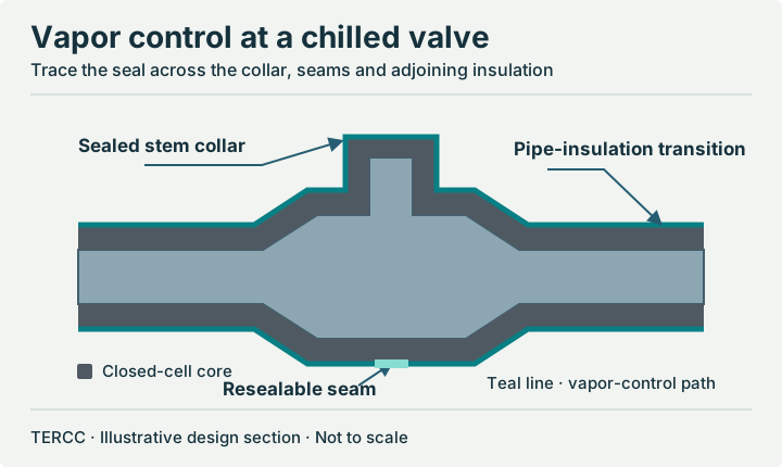
Chilled valve cross-section showing the closed-cell insulation and vapor-control path around the collar, across the closure and into adjacent pipe insulation.
Illustrative construction detail · Actual materials and dimensions are confirmed per project.
Closed-cell elastomeric core
Select the core thickness using fluid temperature, local humidity and the actual fitting geometry. Check the coldest outer points, including seams and penetrations.
Vapor-control system
Continue the vapor-control path across the stem collar and pipe transitions. Whether a separate facing is needed depends on the selected material system and service conditions.
Serviceable seam
Agree how to reseal the cover after removal. Inspect the refitted joint under representative humid operating conditions.
Compare materials by service →

Product views and construction details

Compare alternate views and see how the jacket opens, fits or fastens.
See the full image gallery →
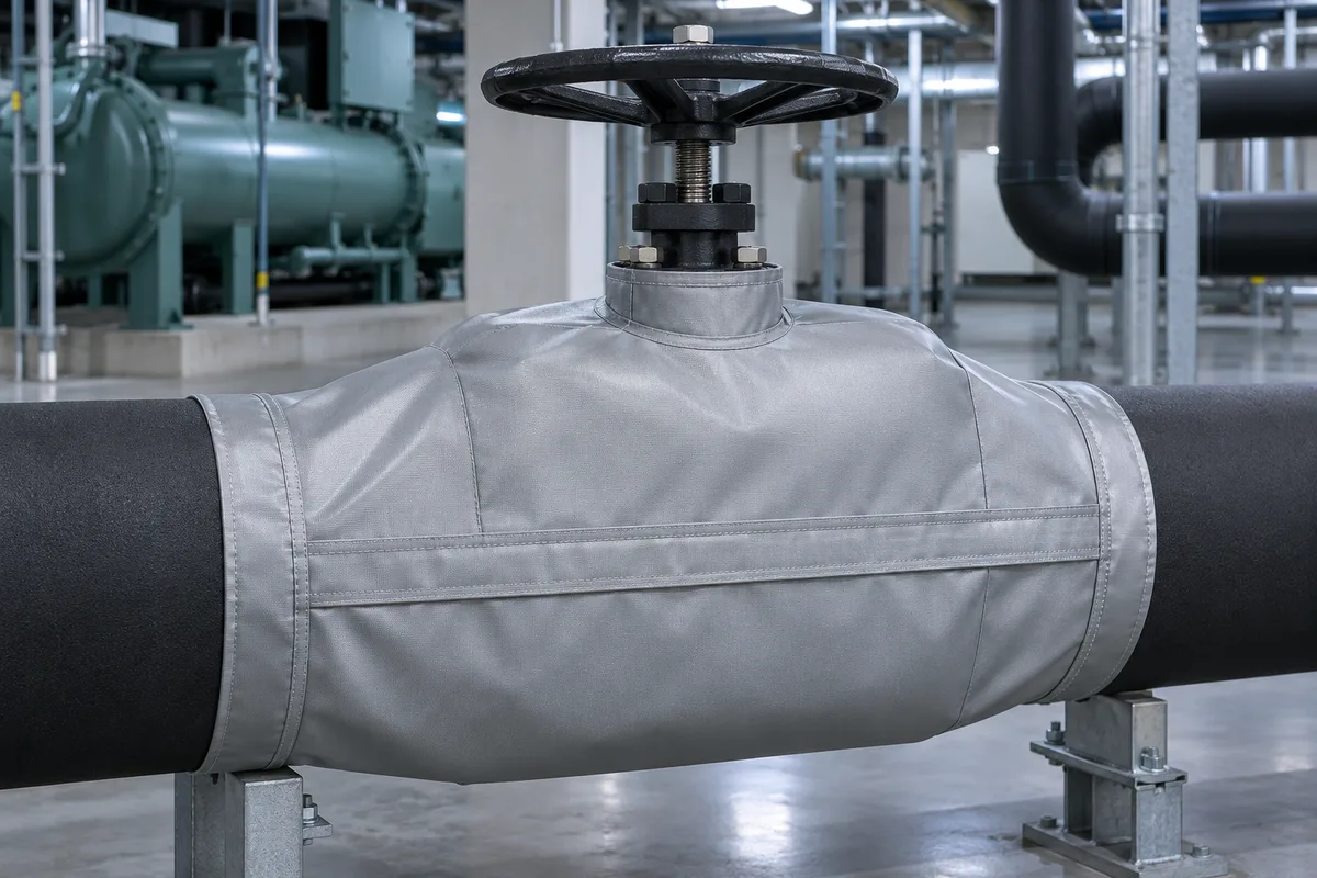
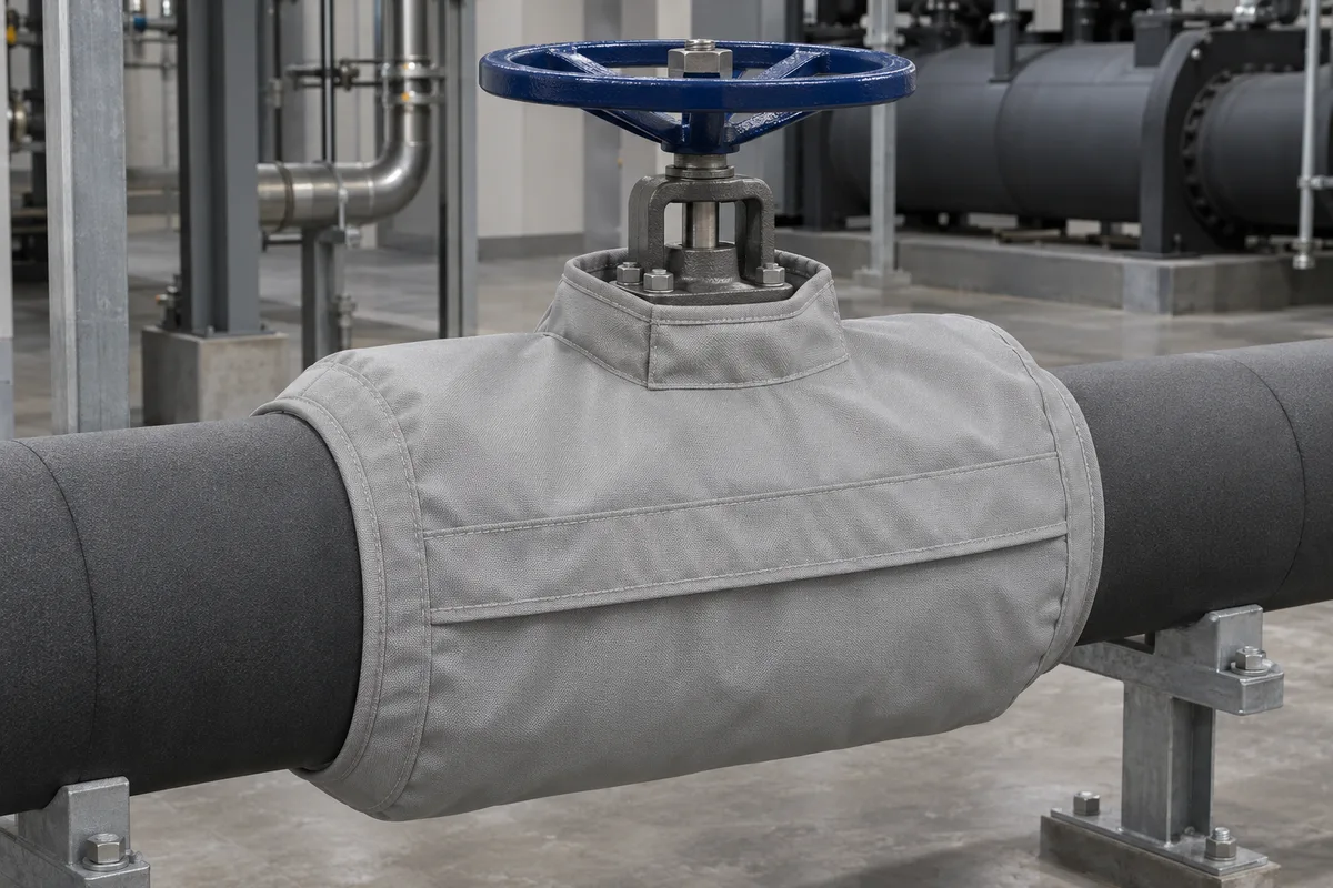
Chilled-water valve jacket concept with an overlap and adjacent pipe insulation
Alternative design · installed view · Design illustration
Open image ↗
Cutaway showing closed-cell core, vapour-control facing and resealable seam at a cold valve
Cold-service detail · Design illustration
Open image ↗

Design and specifications

A continuous vapour-control layer around the stem, closure and end transitions addresses weak points that a plain fabric wrap leaves open.

Shape and construction
Serviceable insulated shell with resealable seams and end transitions
Facing, core and hot face
Closed-cell elastomeric core with compatible vapour-control facing, sealed stem collar and closed-cell pipe-insulation transitions.
Nominal core thickness
Calculate from minimum fluid temperature, maximum ambient humidity and the actual fitting geometry; verify the resulting thickness fits the access envelope.
Installation and closure
Resealable vapour-control overlap with an agreed method for restoring the seal after service.
Dimensions to confirm
Fitting OD and width, existing insulation thickness, stem geometry, minimum water temperature, maximum ambient temperature and RH.

These are options for a custom quotation. Confirm the assembled materials, dimensions, service limits and finish in writing.

Review the construction detail

review the closed-cell layer and how the vapour seal joins adjoining insulation.

Compare the product views above ↑

Industry construction reference →

Operating temperature and expected result

Keep the coldest accessible outer surface above site dew point under agreed humidity conditions; inspect seams and metal penetrations.

Agree the conditions, measurement points and target for the proposed cover before quoting. Record the complete assembly’s approved service limits separately from the target outside-face temperature.

Compare thickness, surface temperature and heat loss →

Chilled water · dew-point example

Use the air temperature and relative humidity around the installed fitting. With 7 °C chilled water, the design must keep the coldest exposed jacket surface above the site dew point, with an agreed margin.

Approximate dew point: 20.1 °C

This indoor estimate uses the Magnus formula over water. It establishes a surface target. Thickness depends on fitting geometry, conductivity and the vapour-control design. Check seals, stem openings and pipe transitions after refitting.

Armacell condensation-control bulletin · WMO humidity formula

What to send us

Send minimum fluid temperature, ambient temperature and humidity, existing insulation details and access frequency.

Include a drawing or scaled photos, quantity and delivery location. Once the key measurements are available, we can review a CAD drawing or annotated design together.

Equipment in the field

Use a site photo like this to show nearby pipework, access obstructions and service points. Send your own photos from two angles, with a scale reference in the same plane as the dimensions.

Prepare a photo set →
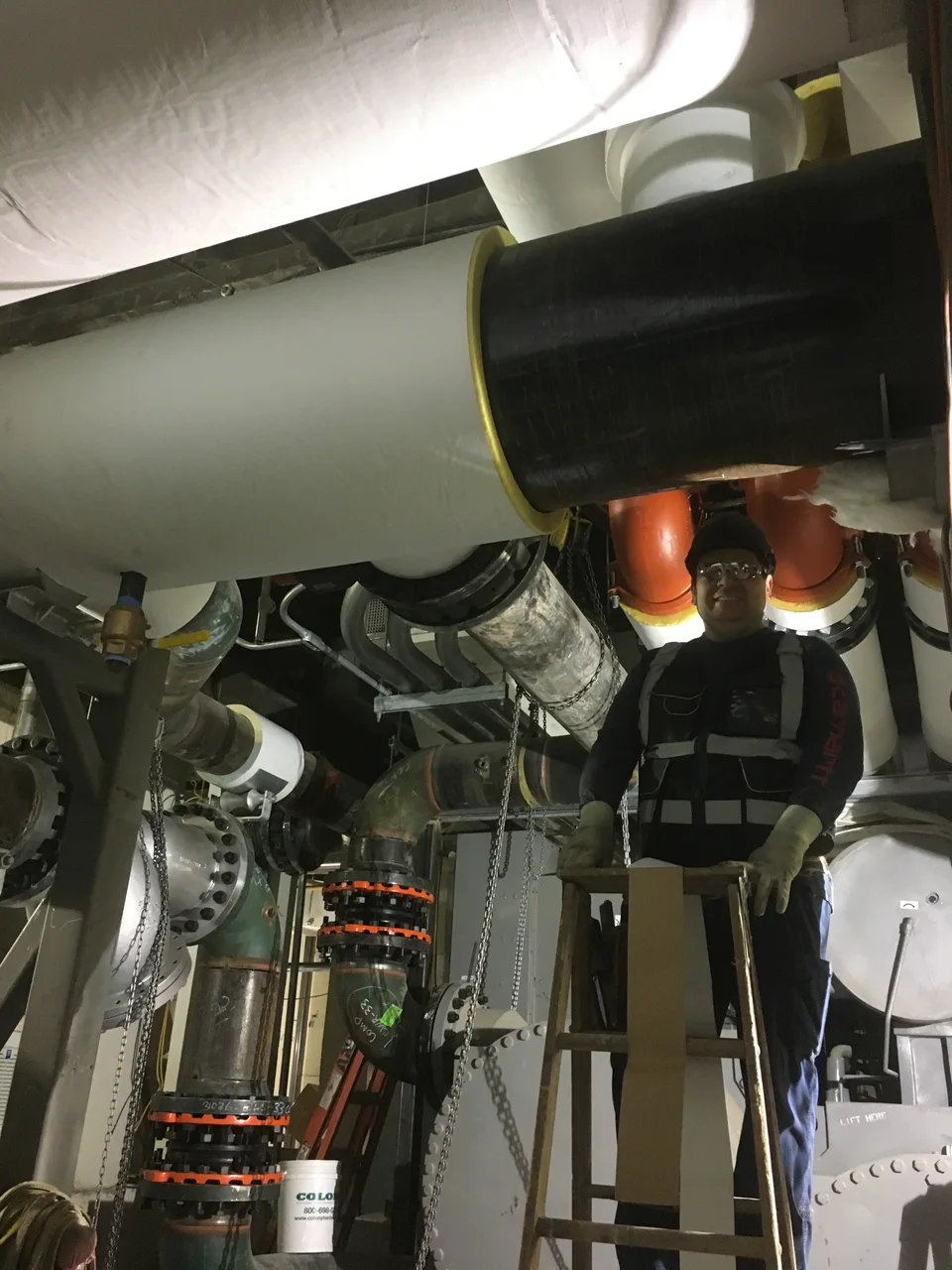
Overhead pipe insulation being installed in an operating-area chiller room
Installation context photo · Pipe insulation work in a chiller room. Installation of pipe insulation in the chiller room by MTA Capital Construction Mega Projects / Wikimedia Commons · CC BY 2.0 · Resized and converted to WebP
Request a Quote →